Present study-Wave Energy
Research of Division of Wave Energy
Research and development of wave energy converter at Saga University
後ろ曲げダクトブイ、浮体型振り子式波力発電装置の実用化を目指し、各装置の高効率化および設計手法の確立を目的として、模型を用いた水槽実験、数値解析コードの開発を行っている。
1. Backward Bent Duct Buoy : BBDB
2. 浮体型振り子式波力発電装置(Floating Type Pendulum Wave Energy Converter : FPWEC)の開発
3. 渦法による浮体構造物の非線形波浪中挙動解析法の開発と波力発電装置の性能解析への適用
4. 固定式振動水柱型波力発電装置(Fixed Oscillating Water Column-Type Wave Energy Converter)の開発
1. Backward Bent Duct Buoy : BBDB
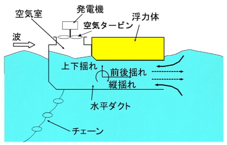
BBDB is a floating oscillating-water-column type wave power generator, which is composed of an L-shaped duct, a buoyant body, a turbine, and a generator.
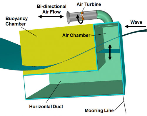
Backward Bent Duct Buoy (BBDB)
1.1 Performance
(1) Experimental study
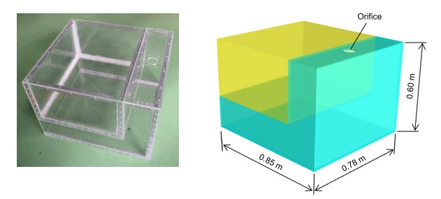
BBDB model
Two-dimensional tank tests were carried out at Ocean Fluid Energy Demonstration Test Tank in Saga University (18 m in length, 0.8 m in width and 1 m in water depth ). The primary conversion efficiency of a small acrylic BBDB model, which has 0.85 m length, in the regular wave was measured. The primary conversion efficiency is defined as the ratio between the wave power and the pnumatic power. The wave height of the regular wave is 0.03 m - 0.05 m. The generator and turbine load was simulated by the orifice provided in the upper part of the air chamber.
The primary conversion efficiency of the same model was measured in a large-sized tank ( 65 m in length, 5 m in width and 7 m in water depth ) in Research Institute for Applied Mechanics, Kyushu University.
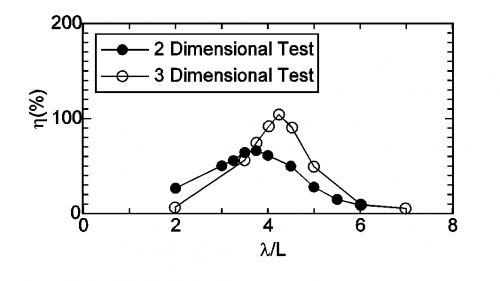
In the two-dimensional experiment, the maximum of the primary conversion efficiency was about 70%. In the three-dimensional experiments, the primary conversion efficiency reached 100% at a specific frequency. This is because the wave incidents from multiple directions due to the diffraction effect of the floating body.
 |
|
primary conversion efficiency of BBDB in two- and three-dimensional experiments |
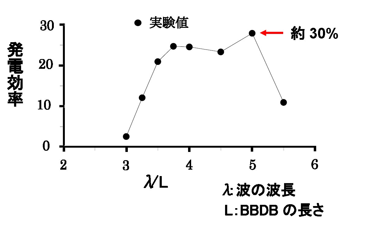
The power generation of a BBDB model, which was equipped with an air turbine and a generator, was measured in a large tank. The model was 2.5 m in length, 2.3 m in width, 1.8 m in height, 0.5 m in draft. An impulse turbine with stationary guide vanes developed at Saga University was used. The maximum power generation efficiency was about 30%.
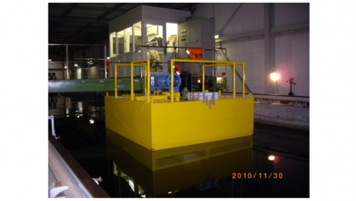 |
| BBDB model with air turbine |
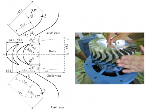 |
| Impulse turbine developed at Saga University |
|
Generatiing efficiency of BBDB |
The power generation of the BBDB model was measured in the waters off Nokojima island, Fukuoka in 2011.
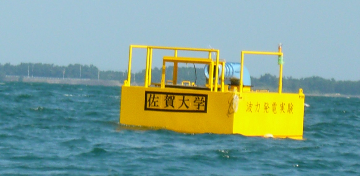
Sea trial of BBDB
(2) Numerical study
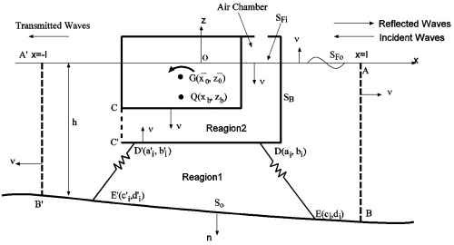
To evaluate the primary conversion performance in the regular wave of BBDB, a two-dimensional numerical calculation method was developed. A BBDB moored with a linear spring was assumed. The motion, the pneumatic pressure, elevation of the water surface in the air chamber, and the primary conversion efficiency of the BBDB were calculated. In the calculation, the velocity potential was assumed, and the boundary element method was used. The air in the air chamber was assumed to be compressible. State equations, mass conservation equations, energy equations have been solved.
 |
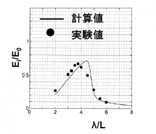 |
| BBDB model | Primary conversion efficiency |
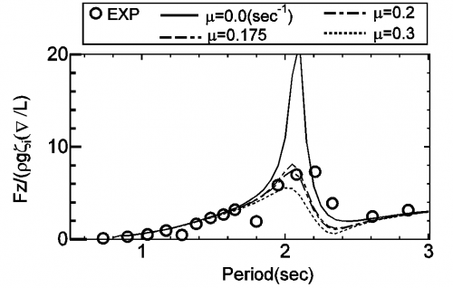
The calculation method was verified compared with the experiment result. The figure shows the vertical wave exciting force acts on the fixed BBDB. The figure shows the vertical force acting on the BBDB when the buoy was forced-oscillated in the vertical direction. The white circle shows the experimental value, and each line shows the calculated value corresponding to the friction of the water surface in the air chamber.
 |
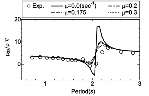 |
| Wave exciting force acts on BBDB | Added mass coefficient |
1.2 Drift force
(1) Experimental study
In general, the floating body drifts downward, but the BBDB drifts to the weather side in a specific frequency band. The mooring costs of the buoy can be reduced because this property mitigates mooring forces. To clarify this characteristic, the drifting force acting on the model was measured in a two-dimensional water tank. In the figure, in the region of λ / L = 5 to 6.5, a drifting force become negative. (λ:length of a incident wave、L:length of BBDB)
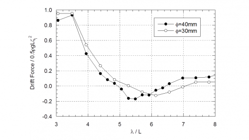 |
| Drift force acts on BBDB |
(2) Numerical study
The motion of BBDB with no mooring in the waves was calculated by using the MPS method. It showed that negative drift force acts on BBDB.
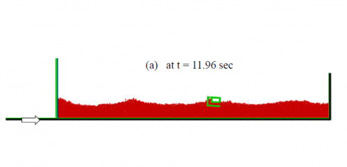 |
| Motion of BBDB in the waves |
2. Floating Type Pendulum Wave Energy Converter : FPWEC
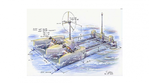 |
| Floating type pedulum wave energy converter proposed by Watabe |
A floating type pendulum wave energy converter (FPWEC) proposed by Watabe is composed of a pendulum, a float and a power take-off system.
(1) Experimental study
Firstly, the load characteristics of FPWEC model with a servo motor and motions of the floating body in regular waves were investigated experimentally. As the result, the maximum primary conversion efficiency of 98% was achieved.
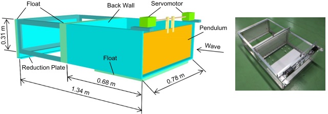 |
| Model of floating type pendulum wave energy converter with servo motor |
Next, the power take-off system which consisits of a rectifier, a generator, a belt and pulleys was installed in the model, and the generating tests were carried out.
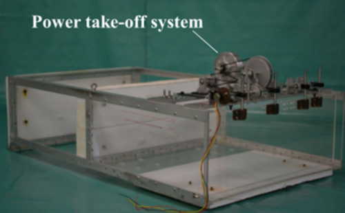 |
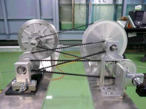 |
| Model of FPWEC | Power take-off system |
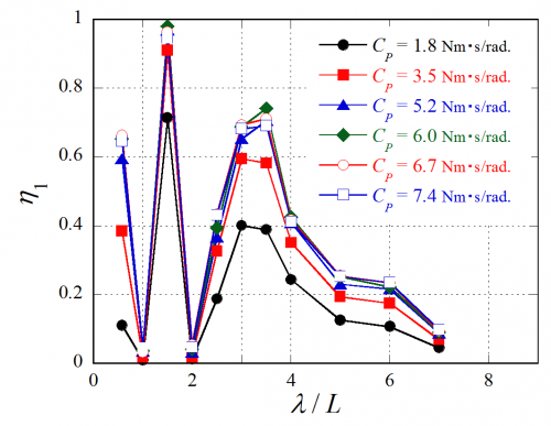 |
 |
| Change in primary conversion efficiency due to damping coefficient Cp | Change in generating efficiency due to electric resistor R |
| (λ:wave length, L:length of water chamber for pendulum) | |
(2) Numerical simulation
To evaluate the primary conversion efficiency of FPWEC in regular waves, motions of the pendulum and the floating body, 2-dimensional numerical simulation using the boundary element method was carried out.
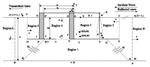 |
|
Simulation model based on boundary element method
|
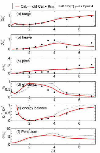 |
|
Comparison between experiment and numerical simulation on motions of floating body in surge, heave and pitch directions, primary conversion efficiency, rotational angle of pendulum |
3. 渦法による浮体構造物の非線形波浪中挙動解析法の開発と波力発電装置の性能解析への適用
波力発電装置は入射波エネルギー吸収装置で、装置の最適設計においては、装置内の可動部の固有周期を、海域の卓越波の周期に一致させる手法が採用されます。このような共振状態において、 浮体型装置では、浮体運動に伴い浮体端部から生じる渦の生成と流体内への粘性拡散や、浮体表面の壁面摩擦等の流体の粘性に伴うダンピングが浮体運動や発電効率に大きく影響するため、装置の性能評価のためには、流体の粘性影響や物体表面から発生する渦の影響を直接考慮できる粘性流体解析法が必要となります。
センターでは、このような目的に適した手法として, 粘性流体を対象として、“渦法による2次元浮体構造物の非線形波浪中挙動解析法”を提案しました。この方法は、以下のような特徴を持っています。
① 流速と渦度を未知量とする“渦度方程式”の解法には、フラクショナル・ステップ法を用いて、時間方向の1ステップの計算を、前半のConvection stepと後半のDiffusion stepの2段階で計算する。速度ベクトルの非回転成分計算を行う前半のステップでは、速度ポテンシャルに関する境界積分方程式に、非線形自由表面条件、水底条件、浮体表面条件 、波の放射条件を代入して解くことにより、時々刻々、移動する自由表面と浮体表面位置を追跡する。
② 後半のステップでは、渦度の粘性拡散の計算にCore-Spreading法を用いる。
③ 物体境界面からの渦度の発生方法に関しては、滑らかな物体表面については渦層モデル、物体の角部についてはVorticity sheddingモデルの2つを併用する。
④ 物体表面に働く流体圧力の計算には、Uhlman (1992)によって提案された、粘性流体の基礎式から導かれた“総エネルギーに関する境界積分方程式”を用いる。
この計算法を、一様流中の円柱周りの流れ、没水平板の鉛直運動, 係留された矩形や三角形断面浮体の波浪中運動に関する計算結果と実験結果と比較することにより, 提案した計算手法の有効性を示しました。この計算手法の提案で、日本船舶海洋工学賞(論文賞)、日本造船工業会賞、日本海事協会賞の3賞を受賞(2016)しました。
浮体型波力発電装置“後ろ曲げダクトブイ(BBDB)”
この計算手法を、浮体式の振動水柱型波力発電装置“後ろ曲げダクトブイ(BBDB)”の一次変換(波パワーから空気パワーへの変換効率)性能評価に適用して、BBDBの運動、空気室内の水面変位と空気圧力、一次変換効率に関する計算値は、水槽実験による実験値とよく一致することを確認しました。
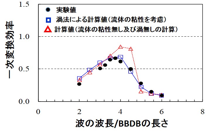
BBDBの一次変換効率の周波数特性
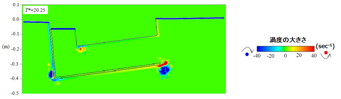
BBDB周りの渦度分布
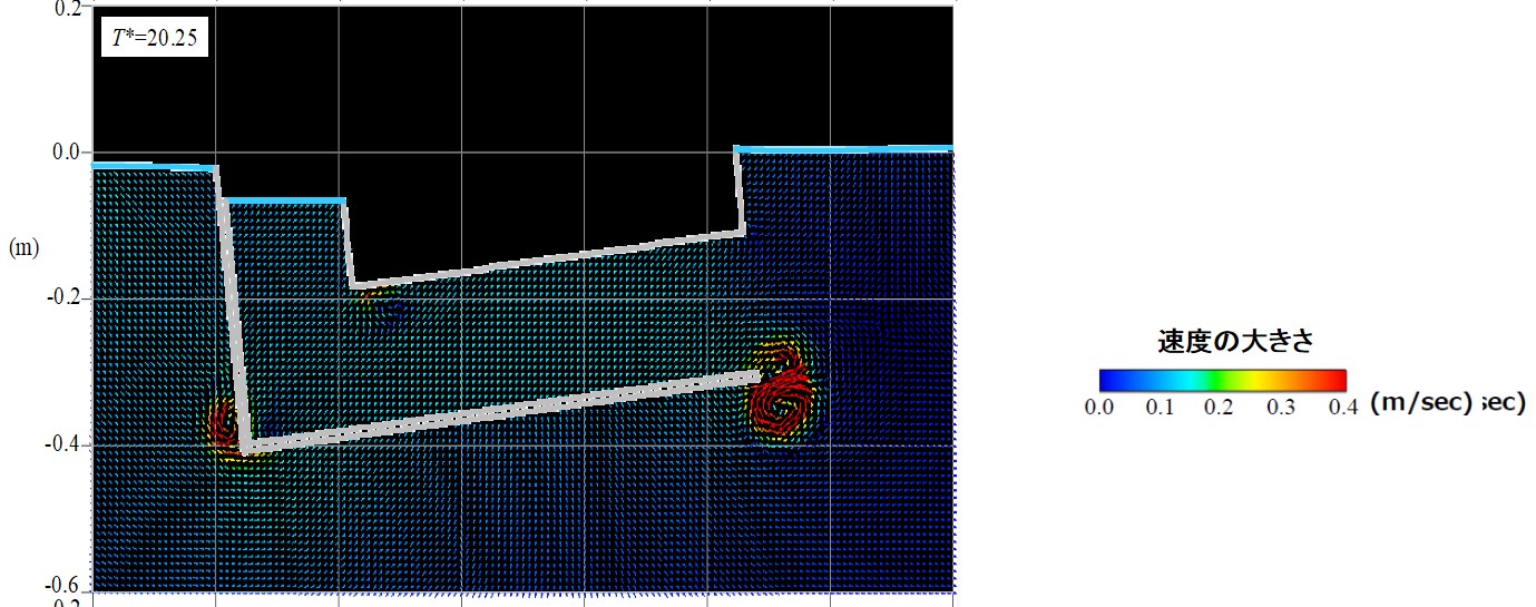
BBDB周りの流速ベクトル
4. Fixed Oscillating Water Column-Type Wave Energy Converter
A fixed oscillating water column (OWC)-type wave energy converter is composed of an air chamber, an air turbine and a generator and is expected to be safe even under storm conditions.
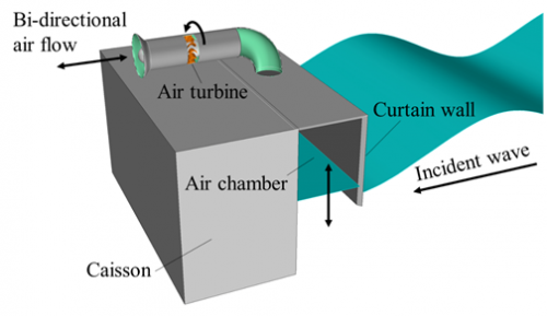
Fixed oscillating water column-type wave energy converter
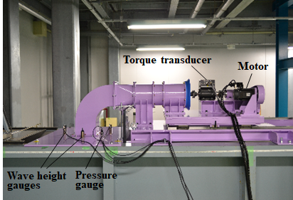
The effects of the air chamber length and the turbine geometry on the efficiency of fixed OWC model with impulse turbine having fixed guide vanes was investigated experimentally. In this experiment, the turbine was driven by a motor.
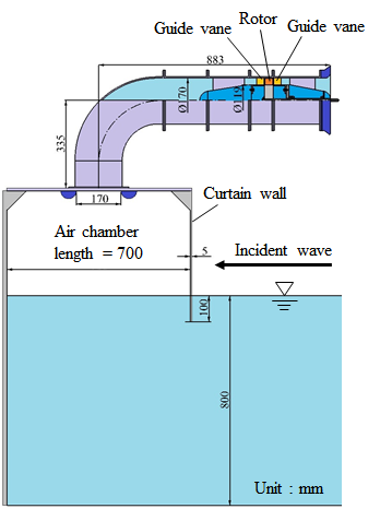
Model of fixed OWC-type wave energy converter
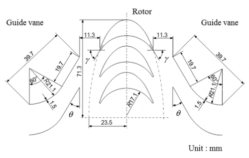
Impulse turbine with fixed guide vane
(γ:rotor inlet/outlet angle, θ:setting angle of guide vane)
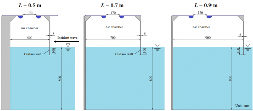
OWC model with different chamber length
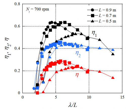
Effect of chamber length on efficiencies
(η1:primary conversion efficiency, η2:secondary conversion efficiency, η:product of η1 and η2, λ:wave length)
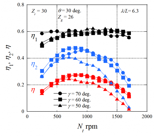
Effect of rotor inlet/outlet angle on efficiencies
(Zr:number of rotor blades, θ:setting angle of guide vane, Zg:number of single stage guide vanes)
Furthermore, the effect of the rotational speed ratio between generator and turbine on the efficiencies was verified using the model equipped with a generator.
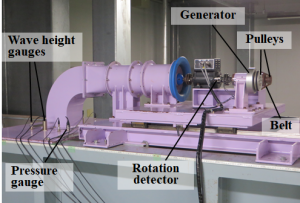
OWC model equipped with a generator
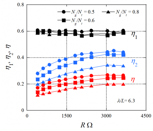
Effect of rotational speed ratio between generator and turbine on efficiencies
(Ng:rotational speed of generator, R:electric resistor)