Present study-Offshore wind energy
Research of Division of New Spar Design for Floating Offshore Wind Turbine
1. Introduction
Spar is one of the promising structures for floating offshore wind turbine (FOWT). In order to lower the center of gravity, the bottom end of spar is filled with fixed ballast and water ballast above. However, it is possible to replace the water ballast part with another non-watertight structure because this part hardly contributes to the statical performance of the floater. In the field of oil and gas production, truss spar was developed with similar concept and reported to be more cost-effective than classic spar [1].
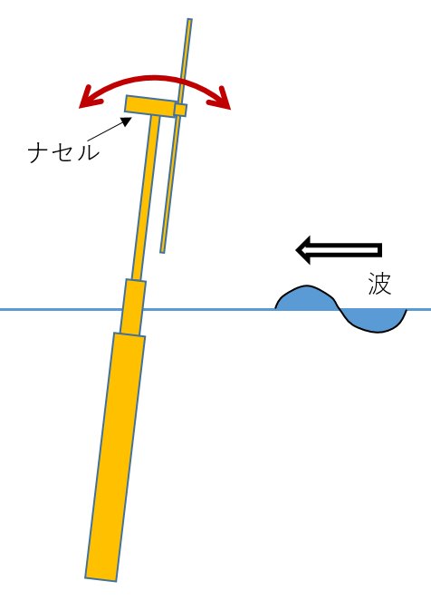
Truss spars have damping plates, called heave plates, to reduce the motion of vertical direction, however pitching motion is more important for FOWT. Therefore, a new type of spar with vertical damping plates, aiming at reduction of not only pitch but yaw motions, is being studied
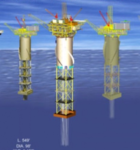 |
| Figure 1. Truss spars (Technip)* |
Reference
* Technip site
2. Models and Tank Tests
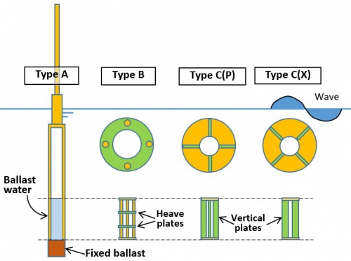
A model tests was conducted in the wave tank in Imari Satellite, IOES (length : 18m, breadth : 0.8m, water depth : 1.0m). Models are shown in Figure 2. Type-A is a classic spar with water ballast inside. Type-B has heave plates like a truss spar. Types-C has four vertical plates. Depending on the direction to waves, Types-C is distinguished between Type-CP and Type-CX. In this test wind turbine was not attached because the they were tested in no wind conditions.
The models are designed to support NREL 5MW turbine [2] with scale of 1/120. The three models had the same principal particulars; the diameters of main part and water plane position were 0.1m and 0.065m respectively and the draft was 0.797m. The models have almost the same stability (W*GM) of 5.5-5.7 Nm. In general, Type-A has larger natural period than others due to the larger mass. On the other hand, the damping coefficients of Types-B and C have larger value than Type-A corresponding to the directions of the damping plates.
 |
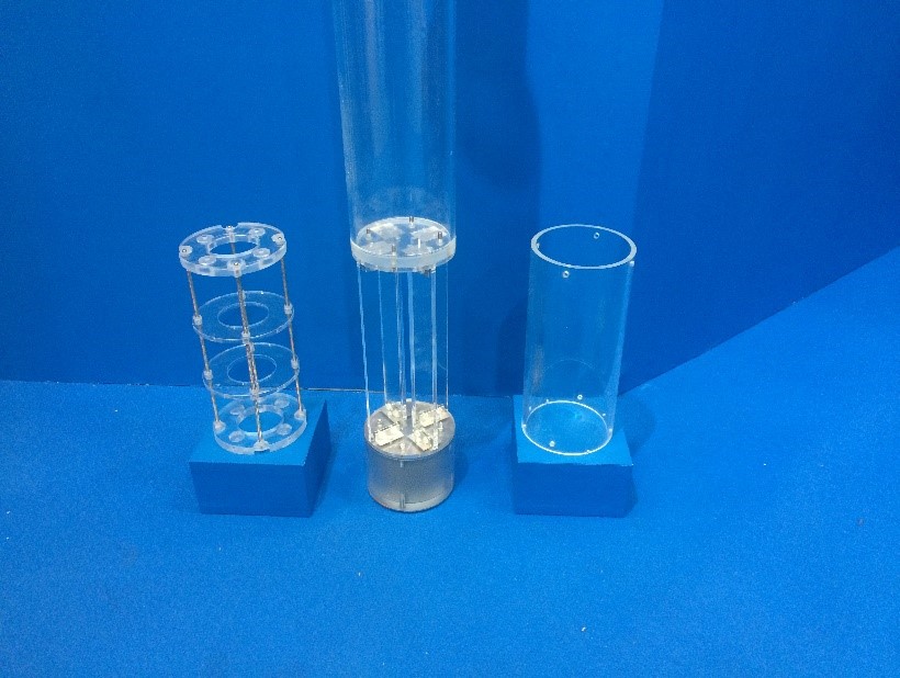 |
| Figure 2. Shapes of spar models | |
3. Response in Waves
RAOs of pitch motion and horizontal acceleration at nacelle are compared in Figure 3 and 4 respectively. Pitch amplitudes of Types CP and CX become smaller than Type-A at the wave frequency closest to resonance. On the other hand, the reduction of nacelle horizontal acceleration appears in wide range of wave frequencies. The reason is that the ratio of pitch amplitues of Types CP and CX to Type-A is about 90% even in high frequency range. This result suggests that Type-C spar has a possibility of cost and motion reduction The optimization of the vertical plates is under consideration.
 |
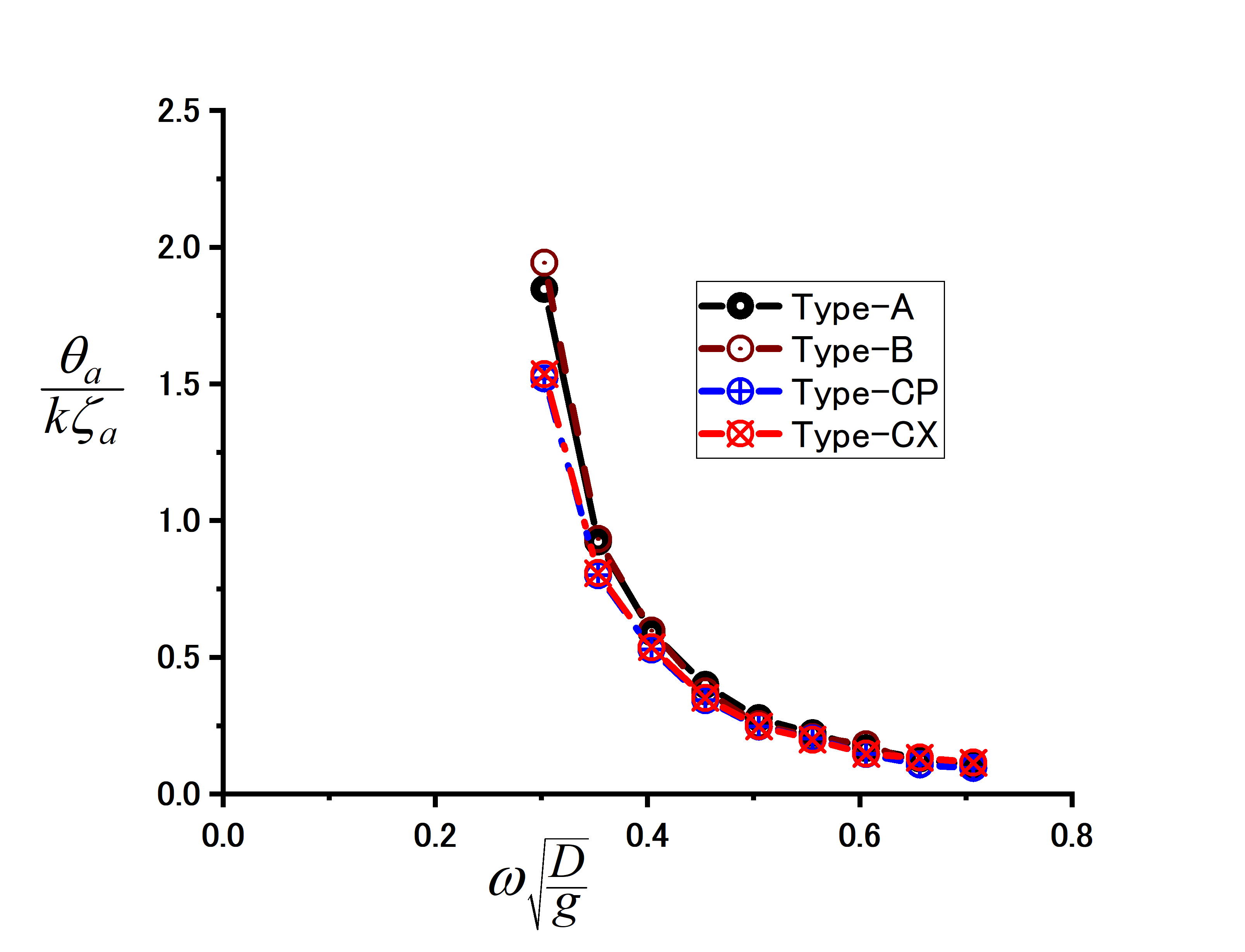 |
| Figure 3. RAOs of pitch motion | |
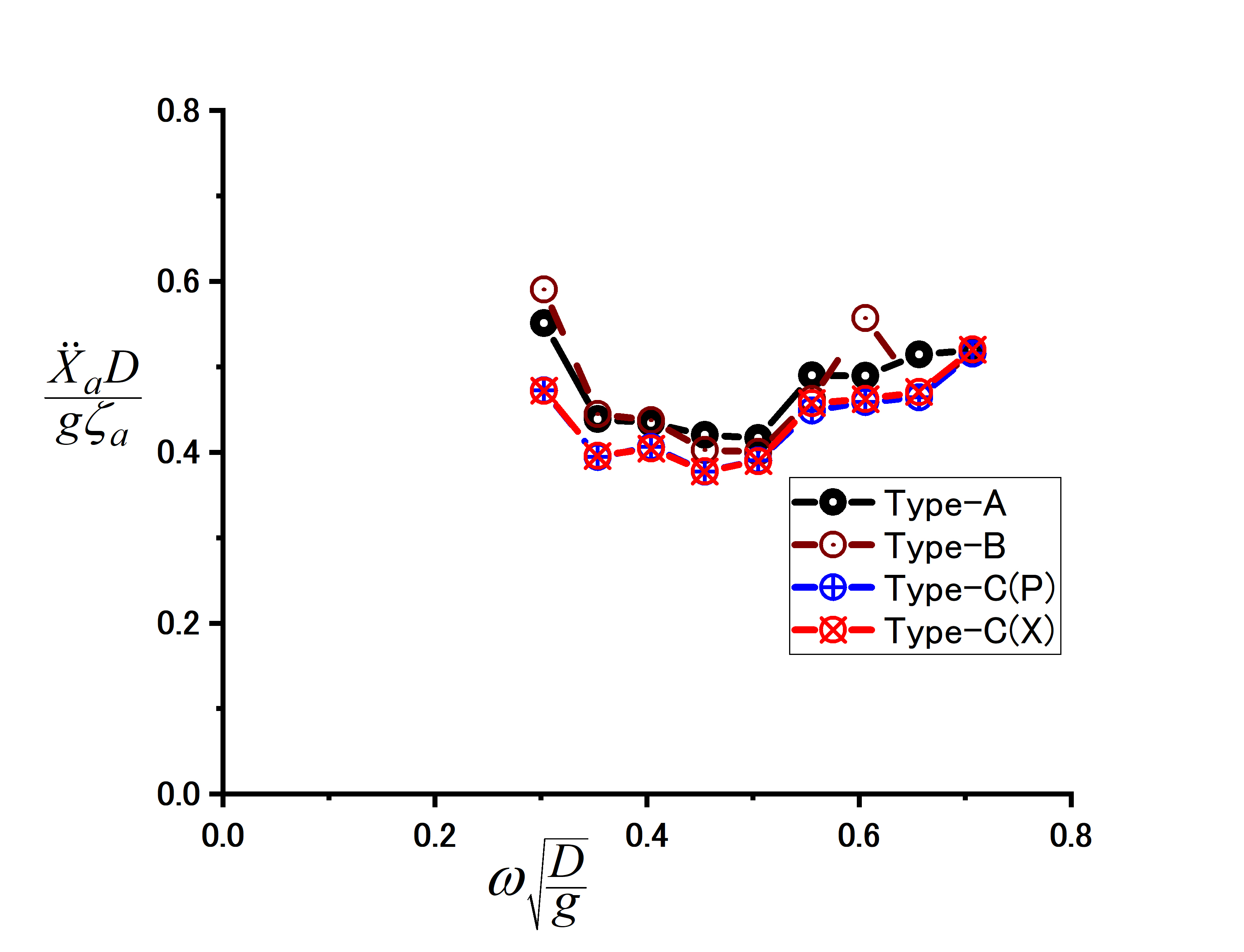 |
| Figure 4. RAOs of horizontal acceleration at nacelle |
References
[1] A.S. Bangs, J.A. Miettinen, T.P.J. Mikkola, et al., “Design of the Truss Spars for the Nansen / Boomvang Field Development”, Proceedings of Offshore Technology Conference, 2002.
[2] J. Jonkman, S. Butterfield, W. Musial et al., “Definition of a 5-MW Reference Wind Turbine for Offshore System Development”, Technical Report NREL/TP-500-38060, 2009.