Present study-tidal energy
Research of Division of Tidal & Ocean Current Energy
Research and Development of Tidal Stream and Tidal Range Power Units
1. Research and Development of Counter-Rotating Type Power Units
1.1 Mechanism and Advantages of Counter-Rotation
A counter-rotating type power unit, where tandem impellers/propellers/runners drive reasonably inner and outer armatures in a unique generator as shown in Fig.1, was invented initially by Research Professor Kanemoto. The outer armature rotates in the counter rotational direction of the inner armature at the same rotational torque with making the relative rotational speed faster, while the tandem impellers counter-rotate absorbing the same angular momentum. Such operations bring out promising advantages as follows.
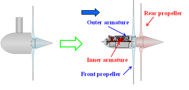
Fig.1 Concept of counter-rotating unit (downstream type)
(a) Downsizing:The unit is downsized as the relative rotational speed is faster, namely which not only decreases the armature diameter, number of the poles and the individual rotational speed (effective to suppress the cavitation), but also increases the induced voltage.
(b) Mooring with one cable:The unit can be easily moored with one cable in the tidal stream without a solid mounting bed, owing to counter-balance the rotational torque (see Fig.2).
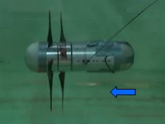
Fig.2 Tidal stream power unit moored with one cable (downstream type)
(c) Keeping slow steady:The impeller work never discharges swirling flow and never disturbs the tidal stream owing to counter-balance the angular momentum.
(d) Supporting every marine circumstance:The unit can be provided to every marine circumstances at arbitrarily rotational speeds while the rotational torque is counter-balanced.
1.2 Counter-Rotating Type Tidal Range Power Unit
At a tidal range power station with a traditional type hydroelectric unit, a pair of the units must be prepared uselessly. The counter-rotating type tidal range power unit is, however, fortunately effective for the bidirectional flows, namely rising and ebb tides at the power station as shown in Fig.3, because the flow discharged from the rear runner (impeller) is in the axial direction while the swirl-less flow attacks to the front runner. Figure 4 shows the hydraulic efficiencies ηh of Runner D34 and D43, where Runner D43 means that the flow direction is changed from the direction for Runner D34. The overall efficiency is scarcely affected by the number of the blades, though the efficiency of the front runner differs from the efficiency of the rear runner. That is, the counter-rotating type is effective for the bidirectional flows, and then the profiles have been being optimized.
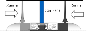
Fig.3 Counter-rotating type tidal range power unit (bidirectional stream type)
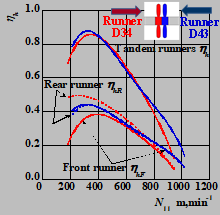
Fig.4 Hydraulic efficiency at the bidirectional flows
1.3 Counter-Rotating Type Tidal Stream Power Unit
Superiority of the counter-rotating type power unit has been recognized in the world, and then New Energy and Industrial Technology Development Organization (NEDO) started supporting research and development works for this type tidal stream power unit at the year 2013. The prototype was provided for field tests at offshore, Nagasaki Bay, on October 2017 (see Figs.5, 6 and 7). The test results verified and guaranteed not only the safety operation but also the high output CP as shown in Fig.8, where λ is the tip speed ratio, ω is the angular speed and T is the rotational torque. That is, the unit has joined the highest honor rank of the tidal stream power generation. Continuously, the installation, the maintenance, the power stabilization technologies have been being researched and developed to provide the unit to the marine markets. Besides, a portable unit moored with only one cable (see Fig.2) has been being prepared to provide the power for farms, street lights at a bridge, and so on.
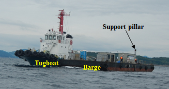
Fig.5 Verification tests at Nagasaki Bay
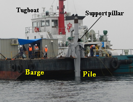
Fig.6 Submerged power unit (generating power)
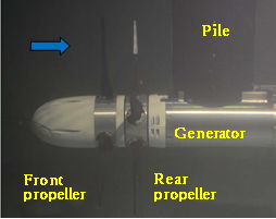
Fig.7 Counter-rotating type tidal stream power unit (upstream type)
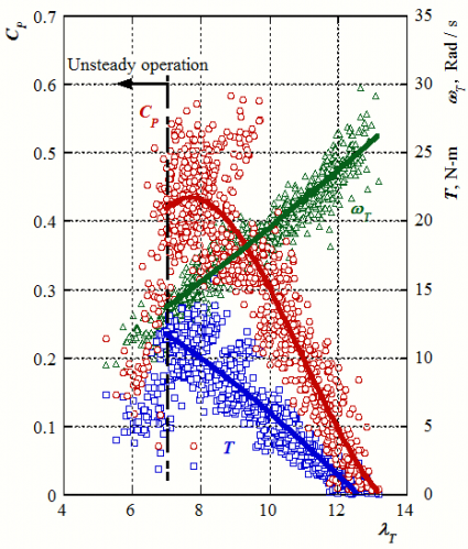
Fig.8 Performance of counter-rotating type tidal stream power unit in verification tests
1.4 Uniting to Onshore Technologies
The counter-rotating technology is fruitfully active in not only offshore but also onshore. The technology for the hydroelectric unit in practical use (see Fig.9) has been being applied to a pumped storage system described latter, the intelligent wind power unit (see Fig.10) has been being provided to the hybrid power system with accompanying the tidal stream and/or range power units. Besides, a power control system equipped with the counter-rotating type pump-turbine as shown in Fig.11 has been bieng researched and developed, to stabilize momentarily fluctuating power from renewable energy resources.
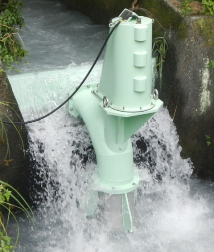
Fig.9 Operation at a ground still of counter-rotating type hydroelectric unit
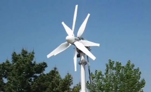
Fig.10 Expanding into offshore wind power plant
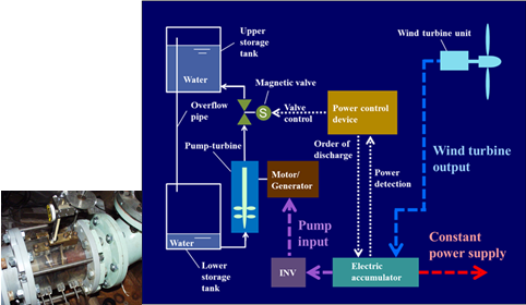
Fig.11 Power stabilizing system with counter-rotating type pump turbine
2. Research and Development of Tidal Stream Power Unit with Flow Collector
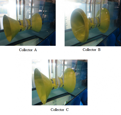
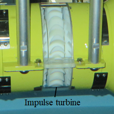
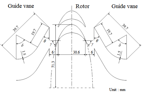
The performances of the bidirectional impulse turbine and the bidirectional flow collector (see Fig.12) for tidal stream power generation are investigated. The combination unit has an advantage that it does not require the yaw angle control mechanism. The bidirectional impulse turbine with fixed guide vane (see Fig.13) for wave power generation is adopted as a tidal stream turbine.
|
|
|
|
Fig.12 Model with flow collector |
|
|
||
|
|
||
|
Fig.13 Impulse turbine |
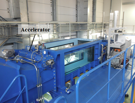
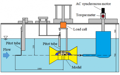
The tidal stream turbine model with flow collector is placed in the test section (see Fig.14) of a circulating water tank. The test section has 2.5m long. The depth and the width of water flow are 0.7m and 1.0m, respectively. In the experiment (see Fig.15), the mainstream velocity of water flow was set at constant, and the turbine rotational speed was changed by a motor.
|
|
|
|
Fig.14 Test section
|
|
|
|
|
|
Fig.15 Arrangement of test device |